|
|
Clark Reliance
TWIP System
|
| TWIP® SYSTEM DETECTION
PROTECTS TURBINES FROM CATASTROPHIC DAMAGE CAUSED BY WATER INFLUX |
|
The most effective
protection against turbine water damage is a well-designed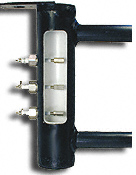 steam plant. However, in the best of plants, the potential
for disaster remains ever present. Industry research indicates
a 35% probability of new equipment damage during the first
five years of operation.
steam plant. However, in the best of plants, the potential
for disaster remains ever present. Industry research indicates
a 35% probability of new equipment damage during the first
five years of operation.
Abnormal conditions can arise quickly. Pump failures, valve
failures, excessive condensation, site flooding and other
events make every steam plant a possible candidate for swift
and unexpected turbine damage.
Designing For Accuracy The ideal water detection device must
fulfill multiple objectives. Foremost, false alarms are unacceptable.
Equally undesired are the cost and nuisance of routine testing
to assure proper equipment performance.
The TWIP System attacks these detection problems directly
and effectively. TWIP combines industry's most successful
sensing Probes with a choice of versatile, high technology
equipment options. TWIP systems of proven reliability and
accuracy are easily tailored for strategic location within
any individual steam plant.
The utmost in performance is achieved in TWIP Systems using
the optional "Voting Logic" trip circuit-employing
a circuit logic in which any 2 of 3 designated probes will
activate the trip circuit when water is present. Voting Logic
virtually eliminates false trips caused by malfunctioning
trip Probes or a single level control failure.
As an option, two trip sensing Probes probes can be installed
in the Water Detector at the same level (trip point), to assure
that even with voting logic circuitry, the trip point is always
at the same single level.
|
| |
| TYPICAL POWER PLANT
INSTALLATION LOCATIONS |
| Drain Pots . Deaerators
. Flash Tanks Feed Water Heaters . Boiler Drums Water Columns
. Storage Tanks . Slowdown Tanks . Separators . System Piping
. Wherever Water Presence Must Be Known. |
| |
| Performing as a small,
independent chamber, the Water Detector is attached to steam
plant equipment or piping.
To facilitate installation, connections may be of the size,
type and orientation best suited to each application. The
Water Detector is available in various materials to withstand
system pressures to 3000 PSI and temperatures to 1100°F:
One or more sensing Probes are located at various chamber
levels to signal the arrival or level of water within. Probes
may be installed at whatever chamber locations are desired.
The Water Detector is where the TWIP system's liquid connections
end - and advanced electronic operation begins.
The performance reliability of the TWIP system is related
directly to the exceptional success of Clark-Reliance Probes.
Clark-Reliance pioneered Probe technology and now continues
to lead in the innovative design and precision manufacture
of water detecting Probes.
Located in the Water Detector, or acting as individual units
in piping, sensing Probes complete an electrical circuit when
water reaches the Probe tip. The completed circuit signals
a relay in the Control Unit which, in turn, can activate an
alarm, drain, pump or other equipment.
Clark-Reliance Probes allow even pure water of ultra-low
conductivity (less than 1 micro mho) to complete electrical
circuits.
ZG and FG Probe service life is extended with low cost Probe
Repair Kits. Kits allow field replacement of components subject
to normal wear factors.
CLICK HERE FOR MORE
INFORMATION ON OUR PROBES
|
| |
| For maximum system accuracy
and personnel safety, the Water Detector should be insulated
with the optional FLEXPAK jacket. The jacket provides a 2inch
thick insulation that is easily removed for routine equipment
inspections. The jacket is suitable for outdoor service. |
| |
| TWIP SYSTEM PROBES
ARE MFG'D FROM PREMIUM MATERIALS THROUGHOUT, PERMITTING
A STANDARD WARRANTY OF 8,760 HOURS ,ONE YEAR). |
| TWIP Control Units, employing
plug-in relays, printed circuit boards and other advanced componentry,
are lightweight, compact and easily installed. Control Units
may be located up to 1000 feet from the Water Detector. In "direct
mode" operation, water that contacts any sensing Probe
immediately completes an electrical circuit to the Probe's corresponding
relay in the Control Unit. |
| |
|
Picture of a Probe
|
| Family Picture of Probes |
| |
|
The relay activates
auxiliary functions such as indicators, solenoid valves, drain
valves, audio/visual alarms, or other protective devices programmed
to counteract or respond to the detection of unwanted water.
Relays may also work in an "inverse" mode, providing
de-activation of electrical controls to prevent false signals
during a power outage.
When water drops below the sensing Probe, the corresponding
relay will revert to its prior state. Relays supply 12 VAC
to Probes and require 115 VAC or 230 VAC 50/60 Hz line supply.
Time delay is available upon request. Each control relay contains
an LED to verify operational status.
TWIP Indicators employ panels of lights to
show the presence of water - in a Water Detector chamber or
at the location of a sensing Probe installed in plant piping.
The Indicator may also be employed to show that a TWIP system
relay has been activated.
Requiring only electrical connections, one
or more Indicators may be quickly and easily installed in
control rooms or other key locations throughout the plant.
Indicators use light emitting diodes (LEDs) which normally
provide more than 10 years of service. LEDs are red or green.
TWIP Control Units can be wired to operate from two power
sources. Operation can switch automatically between power
sources A and B in the event of outages.
|
| |
| TWIP® SYSTEM GENERAL
SPECIFICATIONS |
- TWIP Systems include
the Water Detector, Water Detector Housing, Probe(s), Control
Unit.
- Major options include the TWIP Indicators, Dual Power Supply Diverter, FLEXPAK Jacket, choice of NEMA Control Unit Enclosure, Integral Junction Box, plus electrical specifications as required.
- Water Detectors and Probes are available for pressures to 3000 PSI and temperatures to 1100°F Water Detectors comply with ANSI B31.1 on request.
- Each Probe comes with a 30" high temperature lead. Use of 18 AWG silicone insulated wire is recommended for TWIP system on-site wiring.
- Relays are furnished for line voltage and frequency as specified. Switch contacts are UL rated at 5A/115 VAC, 8A/230 VAC and 1AM25VDC.
|
| |
| Authorized
Service Center Details (PDF File) |
| |
|