Bristol Babcock Oil Content Monitor Model OPM
3
|
Utilizing low pressure steam to heat
fuel oil/crude oil storage tanks is a common practice. However,
there is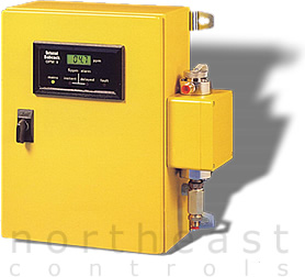 always a concern that oil may enter the condensate system and
cause damage to the boiler internals. Bristol Babcock Limited,
utilizing it's previous experience in this field, now provides
a simple and effective solution to this problem, the OPM 3.
always a concern that oil may enter the condensate system and
cause damage to the boiler internals. Bristol Babcock Limited,
utilizing it's previous experience in this field, now provides
a simple and effective solution to this problem, the OPM 3. |
| General
Description |
|
Specifically designed
for high temperature condensate service, the
OPM 3 Oil Content Monitor is the natural
successor to the much used OT 8 boiler condensate monitor,
utilizing
more
than 35 years of experience
in the design / manufacture of oil content monitors.
The level of oil content is displayed on a back lit LCD digital
indicator. Facilities are provided for remote indication,
recording, and alarm status.
|
| |
| Operating
Technique & Facilities |
|
The sample flows
through a cylindrical glass cell through which a low intensity
beam of infrared radiation is projected. Two silicon
photodetectors are provided to detect and scattered path of
radiation by the oil particles. The angles and field
of view of the detectors have been carefully selected to provide
high sensitivity to oil and very low sensitivity to solids
which may be present in the sample. This, coupled with
the wavelength of light chosen, ensures minimal sensitivity
to water color and other soluble components, and is inherently
self compensating for window fouling, mains voltage variation,
and changes in ambient or sample temperatures.
|
| |
| Indication
And Alarm |
|
Indication of oil
concentration is provided by a back lit LCD digital display,
which gives accurate
indication over
a range 0 - 10 ppm. Two alarm relays are provided,
both factory set, to operate at 5 ppm. One is arranged
to operate immediately 5 ppm level is exceeded, while the
other is provided with a delayed action. The operating
state of each relay is indicated by solid state indicators
on the door of the instrument. Additional and Similiar
indication is also provided for Mains On and Equipment Fault.
|
| |
| Installation
and Maintenance |
|
The unit should be
installed as close as practical to the sampling point. Access
is only required to the top of the cell housing, and front
of the instrument. The connection requirements should
closely follow the instrument. Little maintenance is
required and is confined to a periodic check of zero against
clean water and occasional cleaning of the glass sample cell,
which is mounted in a cell box fixed to the side of the main
instrument case. Access to the inside of the cell is
provided by a hand tightened screw cap, which enables insertion
of a tube cleaning brush. No dismantling is involved.
|
| |
| Specifications |
| Range |
0
-10ppm |
| Accuracy |
±
1 ppm |
| Indication |
LCD Digital
(Resolution 0.1 ppm) |
| Enclosure
Rating |
IP
55 |
| Size |
400 mm
high x 380 mm wide x 150 mm deep |
| Weight |
12
kg |
| Output
Signal |
4 - 20
mA |
| Ambient
Temperature |
-
15 C To + 60 C |
| Clean
Water Requirement |
2 bar
to 8 bar |
| Electrical
Supply |
220/240V
or 110V AC 50/60Hz |
| Power
Consumption |
11VA |
| Relays |
2
off Instanteous and delayed (Delay factor --
set at 20 sec) |
| Contacts |
Single
pole c/o Rating 2.5A at 250V AC |
| Alarm/Fault
Indication |
3
off Instant/Delay/Fault Red LED's on front panel |
| Sample
Pressure |
2 bar
to 8 bar |
| Sample
Flow |
1.0
litres/min |
| Sample
Temperature |
+2C to
+90C |
| Sample
Connections |
Compression
fittings for 10mm outside diameter pipe |
|
|
| Previous
Page |
| |