| |
Jerguson
Series 20 Medium Pressure Armored Gages |
| Pressures
Up To 3270 PSI @ 100ºF / 2285 PSI @ 600° F |
| One of the
simplest techniques for indicating liquid level is by means
of a direct reading device with which the
level can be seen visually. A common method of providing
such visual indication is by installing direct reading gages
in the vessel itself. These direct reading gages are placed
at different locations or points to indicate the liquid height.
More often, separately mounted gage glasses are used to provide
a continuous indication of level over a certain vertical
distance on the vessel.
Standard construction (for Series 20 Gage) includes a one-piece
chamber machined from bar, forged steel covers,tempered glass,
alloy steel bolts and nuts. Select reflex
glass (prismatic) Style Glass or transparent
(clear) glass gage. The recessed gasket seats aid
in positioning and retaining the gasket. Series 20 gages
are available in a wide variety of materials to meet specific
applications. Accessories available include: illuminators
(both Incandescent and Fiber
Optic), non-frosting extensions,
support brackets and insulation jackets. Our 316 Stainless
Steel is dual rated for standard 316 and 316L Grade. Available
in Low Temperature Carbon Steel |
| |
| Features |
- Standard
Chamber Material: Carbon Steel (A696 C), Low Temperature Carbon
Steel (A350 LF2) and 316LSS (A511 Dual Rated for 316SS & 316LSS)
- Tempered Borosilicate Glass conforming to BS3463, JIS B8211, DIN 7080 & DIN 7081
- All gages are Hydrostatically Tested to 1-1/2 times the rated pressure at 100º F (38ºC)
- Wetted Parts Conform to NACE MR.-01-75
- All Parts are ASTM Grade and listed in ANSI 31.3
- Recessed Gasket Seat in Chamber and Cover
- Covers are Shrouded to Protect the Glass Edge
|
| |
| Series 20 Specifications: |
Section Lengths: Gage sections are available in nine standard glass sizes. Longer sizes are constructed with multiple vision slots in a continuous solid bar chamber.
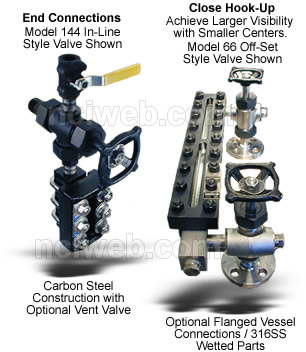
- Connections: Standard connections are at top and bottom and are 1/2" or 3/4" NPT female. Optional connections are available, such as socket weld, flanged or close hook-up (side/side).
- Liquid Chamber: Machined bar stock. The gasket seat is recessed to allow lateral support and facilitate positioning.
- Covers: Forged carbon steel is standard. Optional materials are available such as 316SS. The cushion gasket seat is recessed.
- Bolts & Nuts: Alloy steel is standard, A193 B7 and A194 2H. Optional materials are available. All steel fasteners are "black oxide" treated to prevent rust.
- Glass: Tempered Borosilicate is used to 600° F (316° C). Aluminosilicate is used to 800° F (427° C). Transparent glass may be protected from corrosive media with mica or Neoflon CTFE shields.
- Gaskets: Standard gaskets are precision die cut in proprietary Jerguson dies.
- Finish: All steel parts are finish coated prior to assembly. Stainless steel is not coated.
NOTE: It is recommended that all gages be installed with Jerguson gage valves having safety ballchecks which help provide protection against physical injury and loss of product if glass breakage should occur.
|
| |
| Specify Gage Assemblies by the Figures given below: |
| Fig. 1 |
Fig. 2 |
Fig. 3 |
Fig. 4 |
Fig. 5 |
Fig. 6 |
Fig. 7 Offset Inside |
Fig. 8 Offset Outside |
 |
 |
 |
 |
 |
 |
 |
 |
| Valves |
Valves |
Valves |
Valves |
Valves |
Valves |
Valves |
Valves |
| 63, 143, 73BL & 93 |
64, 144, 74BL & 94 |
66, 146 & 76BL |
67, 147 & 77BL |
63, 143, 73BL & 93 |
64, 144, 74BL & 94 |
146, 147, 66, 67, 76BL & 77BL |
|
|
|
| |
| Series 20 Models and Dimensions |
Sect. Size |
Visible Range |
Overall Length |
Reflex, R-20 Weight |
Transp., T-20 Weight |
| |
in |
mm |
in |
mm |
Lbs. |
Kgs |
Lbs. |
Kgs |
| Single-Section Gages |
| 11 |
3-3/4 |
95 |
5-1/4 |
133 |
8 |
3.6 |
10 |
4.5 |
| 12 |
4-3/4 |
121 |
6-1/4 |
159 |
9 |
4.1 |
14 |
6.4 |
| 13 |
5-3/4 |
146 |
7-1/4 |
184 |
11 |
5.0 |
17 |
7.7 |
| 14 |
6-3/4 |
171 |
8-1/4 |
210 |
12 |
5.5 |
19 |
8.6 |
| 15 |
7-7/8 |
200 |
9-3/8 |
238 |
14 |
6.4 |
21 |
9.5 |
| 16 |
9-1/8 |
232 |
10-5/8 |
270 |
16 |
7.3 |
24 |
10.9 |
| 17 |
10-1/4 |
260 |
11-3/4 |
298 |
18 |
8.2 |
27 |
12.3 |
| 18 |
11-7/8 |
302 |
13-3/8 |
340 |
20 |
9.1 |
30 |
13.6 |
| 19 |
12-5/8 |
321 |
14-1/8 |
359 |
21 |
9.5 |
32 |
14.5 |
| Two-Section Gages |
| 23 |
13 |
330 |
14-1/2 |
368 |
22 |
10.0 |
33 |
15.0. |
| 24 |
15 |
381 |
16-1/2 |
419 |
25 |
11.4 |
38 |
17.3 |
| 25 |
17-1/4 |
438 |
18-3/4 |
476 |
28 |
12.7 |
43 |
19.5 |
| 26 |
19-3/4 |
502 |
21-1/4 |
540 |
32 |
14.5 |
49 |
22.3 |
| 27 |
22 |
559 |
23-1/2 |
597 |
35 |
15.9 |
54 |
24.5 |
| 28 |
25-1/4 |
641 |
26-3/4 |
679 |
40 |
18.2 |
61 |
27.7 |
| 29 |
26-3/4 |
679 |
28-1/4 |
718 |
43 |
19.5 |
64 |
29.1 |
| Three-Section Gages |
| 36 |
30-3/8 |
772 |
31-7/8 |
810 |
48 |
21.8 |
73 |
33.2 |
| 37 |
33-3/4 |
857 |
35-1/4 |
895 |
53 |
24.1 |
80 |
36.4 |
| 38 |
38-5/8 |
981 |
40-1/8 |
1019 |
60 |
27.3 |
92 |
41.8 |
| 39 |
40-7/8 |
1038 |
42-3/8 |
1076 |
64 |
29.1 |
97 |
44.1 |
| Four-Section Gages |
| 47 |
45-1/2 |
1156 |
47 |
1194 |
71 |
32.3 |
107 |
48.6 |
| 48 |
52 |
1321 |
53-1/2 |
1359 |
80 |
36.4 |
122 |
55.5 |
| 49 |
55 |
1397 |
56-1/2 |
1435 |
85 |
38.6 |
129 |
58.6 |
| Five-Section Gages |
| 57 |
57-1/4 |
1454 |
58-3/4 |
1492 |
88 |
40.0 |
134 |
60.9 |
| 58 |
65-3/8 |
1661 |
66-7/8 |
1699 |
100 |
45.5 |
152 |
69.1 |
| 59 |
69-1/8 |
1756 |
70-5/8 |
1794 |
106 |
48.2 |
161 |
73.2 |
| Six-Section Gages |
| 68 |
78-3/4 |
2000 |
80-1/4 |
2038 |
120 |
54.5 |
187 |
85.0 |
| 69 |
83-1/4 |
2115 |
84-3/4 |
2153 |
127 |
57.7 |
196 |
89.1 |
| Seven-Section Gages |
| 78 |
92-1/8 |
2340 |
93-5/8 |
2378 |
140 |
63.6 |
221 |
100.5 |
| 79 |
97-3/8 |
2473 |
98-7/8 |
2511 |
148 |
67.3 |
230 |
104.5 |
| 88 |
105-1/2 |
2680 |
107 |
2718 |
160 |
72.7 |
254 |
115.5 |
| 89 |
111-1/2 |
2832 |
113 |
2870 |
169 |
76.8 |
265 |
120.5 |
|
|
|
|
| |
|
| |
| Support
Files / Links |
| See
Cut-a-Way of Armored Gage |
| Series
20 Models and Dimensions |
| Compare
the Armored Level Gage to the Magnetic Style Level Gage |
| See
Glass Example |
| See
Gage & Valve Assembly Example |
| Pressure
and Temperature Ratings |
| Dimensional
Information |
| Example
Of Electrical Heat Tracing |
| Lights and Accessories |
| Reflex
Gage Cutaway |
| Examples
Of Transparent And Reflex Glass |
| Download
Installation, Operation and Maintenance Manual |
| |
| |
| |
| Previous
Page |
| |
| |