 The
simplest and least costly method of liquid level indication
is the tubular gage glass. Two slightly different designs are
available. Both are simply transparent vertical tubes
with their lowest visible point connected to the tank or boiler
at the lowest level of interest. The top of the glass may be
open to the atmosphere if the tank is open or to the unfilled
part of a closed vessel above or at the highest level permitted.
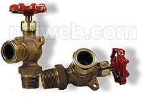
Isolating valves are placed above and below the gage glass
connections. 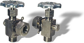 One choice is a gage glass with slow closing valves and
the second choice are valves with quick closing type where
a one quarter turn of the valve spindle will change the valve
from the fully open to the fully closed position. The valve
spindles are fitted with levers to which chains may be attached
in order to operate the valves from ground level if the vessel
is located at a higher position. Drain valves or cocks may
also be installed below the gage glass to remove any solid
material that may collect. One choice is a gage glass with slow closing valves and
the second choice are valves with quick closing type where
a one quarter turn of the valve spindle will change the valve
from the fully open to the fully closed position. The valve
spindles are fitted with levers to which chains may be attached
in order to operate the valves from ground level if the vessel
is located at a higher position. Drain valves or cocks may
also be installed below the gage glass to remove any solid
material that may collect.
Since many tanks and pressurized vessels are not under continuous
supervision, a broken gage glass may allow a large amount
of fluids to escape. To prevent this, the lower valve on
the gage glass is often equipped with a safety shutoff device
consisting of a stainless steel ball which closes off the
fluid passage when the glass breaks. One disadvantage of
this type of safety device is that it requires more maintenance.
Under normal conditions, the steel ball remains in the recess
in front of the valve seat. However, when the gage glass
breaks, the sudden rush of fluid through the valve will force
the ball against the valve opening. This shuts off the flow
out of the broken glass.
The gage glass is usually surrounded by a number of metal
rods or transparent shield to protect the glass from breakage
and the operator from flying particles in case the gage glass
shatters.
The use of tubular gage glasses is limited to lower pressures
and temperatures, and restricted to non-toxic and non-hazardous
material. Tubular gage glasses should not exceed 750 mm in
length. If the level range to be observed exceeds this length,
then two or more gage glasses should be installed so that
they overlap.
|