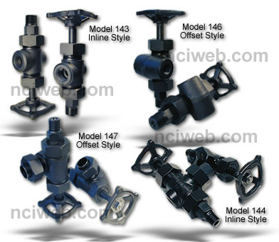
Jerguson Isolation Valves Series 140 |
||||||||||||||||||||||||||
|
||||||||||||||||||||||||||
| MATERIALS | ||||||||||||||||||||||||||
| No. 140 Series Valves have steel bodies and malleable iron handwheels. Long life is assured by the use of stainless steel for the stem, and ballcheck. Materials used to conform to or exceed requirements of A.I.S.I., A.S.TM. and/or A.P.I. - A.S.M.E. for recommended pressures. | ||||||||||||||||||||||||||
| SPECIAL CONNECTIONS (extra charge) | ||||||||||||||||||||||||||
|
No. 140 Series Valves can be furnished upon request with flanged, socket welding, solid shank (non-union) and Spherical Union Connections. The use of Spherical Unions on inlets and outlets with top and bottom connected gages is particularly valuable lest the vessel connections are not perfectly parallel. This construction will compensate for up to 10° misalignment of vessel tapping in any direction from the stem axis and up to plus or minus variation from mean centers. The same compensation may be had on side connected gages using single spherical tailpieces on the outlet connections. |
||||||||||||||||||||||||||
| ROUGHING DIMENSIONS | ||||||||||||||||||||||||||
| To determine maximum space available for top and bottom connected gage, deduct from center to center dimensions: | ||||||||||||||||||||||||||
| 3½" on Nos. 143 and 146 | ||||||||||||||||||||||||||
| 5-7/8" on Nos. 144 and 147 | ||||||||||||||||||||||||||
|
Note A. ¾" dimension applies to all ½" N.P.T. end connected Reflex and Transparent gages except L-10 which is 1¼". Note B. To determine overall length of ½" I.P.S. nipples add 7/8" to distance between gage and valve. For side connected gages: Refer to bulletin on page selected. Using No. 143 or 144 valves the side centers on the gage and the centers are the same. Using No. 146 or No. 147 valves with offsets inside gage centers, deduct 1¾" from side centers. Using No. 146 or No. 147 valves with offsets outside gage centers, add 1¾" from side centers. |
||||||||||||||||||||||||||
| SPECIAL FEATURES | ||||||||||||||||||||||||||
|
Vertical Rising Ballcheck: No. 147. An additional safety feature in the bottom valve of a top and bottom connected assembly is an optional vertical rising ballcheck on the downstream side of the seat. This arrangement shuts off the flow of liquid in case of fracture of the instrument or connecting piping and eliminates the horizontal ball in the bottom fitting. A ½" male drain is standard. A cap may be furnished on request. Bleed Fitting: A bleed fitting is available making it possible to bleed pressure from the valve and connected instrument without breaking any threaded connections. The bleed fitting is designed so its stem cannot be withdrawn accidentally. It is tapped for 1/8" N.P.T. discharge. |
||||||||||||||||||||||||||
|
||||||||||||||||||||||||||
| Previous Page | ||||||||||||||||||||||||||
 Integral bonnet valves, steel & stainless steel bodies
available. Stainless steel trim with a wide choice
of connections.
Integral bonnet valves, steel & stainless steel bodies
available. Stainless steel trim with a wide choice
of connections.