Air Filters and Filter Silencers
|
|
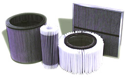 Universal Silencer offers a wide range of sizes
and types of air Filters and Filter Silencers for application
on air moving equipment and internal combustion engines. This
catalog covers our standard "shelf" models, many of
which are stocked for immediate shipment. Special types and configurations,
as well as larger sizes not cataloged, are quoted upon application
to meet specific job requirements. In submitting your inquiry
for a recommendation or quotation, please give full particulars
and conditions, including the following: Universal Silencer offers a wide range of sizes
and types of air Filters and Filter Silencers for application
on air moving equipment and internal combustion engines. This
catalog covers our standard "shelf" models, many of
which are stocked for immediate shipment. Special types and configurations,
as well as larger sizes not cataloged, are quoted upon application
to meet specific job requirements. In submitting your inquiry
for a recommendation or quotation, please give full particulars
and conditions, including the following:
- Type of Equipment (rotary blower, centrifugal compressor,
etc.)
- Volume of air and barometric conditions (CFM at pressure & temperature)
- Inlet flange size on equipment
- Required efficiency of filter media (% arrestance at particle
size in microns)
- Maximum restriction (pressure drop) allowed - including
entrance and exit losses
- If silencing is required, give noise specifications to
be met
- Special finish requirements
- Other pertinent data which should be considered in the
selection
|
| Choice of Models: |
|
|
| *Capacity ranges shown are nominal. Specific
pressure drop considerations may narrow or broaden the range of
capacities. |
| |
| Note: Care should be exercised in
the selection of type and size of Filters and Filter Silencers.
Although this product catalog is designed to assist the user in
proper selections, it may still be advisable to contact Universal
Silencer's engineers for additional assistance. Inquiries are welcome
and will be given prompt attention. |
| |
| Sizing Instructons Pressure Drop Data |
|
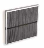 The Filters and Filter Silencers listed on the
following pages are available with a variety of types of filter
panels, each having its own restriction characteristics. Consequently,
the pressure drop data below are presented in such a way that
two components must be added to obtain the total pressure drop
for a specific filter application. One component is the restriction
attributable to the filter housing exclusive of filter panels.
The second component is the restriction through the filter panel
media. The housing pressure drop is given in graph form as a
function of air flow in CFM versus restriction in inches of water
gage. The pressure drop component for the filter panels is charted
in tabular form - giving pressure drop in inches of water gage
at various flows in CFM. The Filters and Filter Silencers listed on the
following pages are available with a variety of types of filter
panels, each having its own restriction characteristics. Consequently,
the pressure drop data below are presented in such a way that
two components must be added to obtain the total pressure drop
for a specific filter application. One component is the restriction
attributable to the filter housing exclusive of filter panels.
The second component is the restriction through the filter panel
media. The housing pressure drop is given in graph form as a
function of air flow in CFM versus restriction in inches of water
gage. The pressure drop component for the filter panels is charted
in tabular form - giving pressure drop in inches of water gage
at various flows in CFM.
Pressure drop calculation example: FSH type
Filter Silencer is required for 2500 CFM air flow. Type
P-11 high efficiency filter panels. Pressure drop limitation
- 3" water gage. Try FSH10-2 (page 4) with nominal rated
capacity of 2750 CFM. Enter graph at 2500 CFM and go vertically
to 10" parameter line. Go left to pressure drop scale
and read 2.6" w.g. FSH10-2 is equipped with two panels,
thus each panel will handle 1250 CFM. Pressure drop chart for
filter panels indicates 0.44" w.g. for P-11 type filter
panel at 1250 CFM. Add 2.6" and 0.44" for total of
3.04" w.g. pressure drop.
|
| |
| Pressure Drop Values - 20" X 25" Panel
Filters (in. w.g.) |
| CFM
Per |
W-2 |
DD-2 |
P-11 |
W-2 & |
W-2 & |
P-8 & |
P-5 |
W-2 & |
DD-2 & |
|
Filter
|
|
|
|
DD-2
|
P-11
|
P-12F
|
|
P-5
|
P-5
|
| 500 |
0.01 |
0.06 |
0.09 |
0.07 |
0.10 |
0.80 |
0.28 |
0.29 |
0.34 |
| 600 |
0.02 |
0.08 |
0.13 |
0.10 |
0.15 |
0.96 |
0.35 |
0.37 |
0.43 |
| 700 |
0.03 |
0.11 |
0.16 |
0.14 |
0.19 |
1.12 |
0.42 |
0.45 |
0.53 |
| 800 |
0.03 |
0.14 |
0.21 |
0.17 |
0.24 |
1.28 |
0.49 |
0.52 |
0.63 |
| 900 |
0.04 |
0.17 |
0.25 |
0.21 |
0.29 |
1.44 |
0.56 |
0.60 |
0.73 |
| 1000 |
0.05 |
0.21 |
0.30 |
0.26 |
0.35 |
1.60 |
0.64 |
0.69 |
0.85 |
| 1250 |
0.08 |
0.31 |
0.44 |
0.39 |
0.52 |
2.00 |
0.83 |
0.91 |
1.14 |
| 1500 |
0.12 |
0.44 |
0.59 |
0.56 |
0.71 |
2.40 |
1.04 |
1.16 |
1.48 |
|
| Note: Pressure drop values indicated
by the graphs on this page include pipe entrance pressure drops
attributable to the atmospheric end of the inlet pipe. These
drops are significant. contributing in some cases as much as 75%
of the total pressure drop, and should not be regarded as excess
restriction due to the filter. However, adding the filter to the
system transfers these pipe drops to within the filter housing
and a pressure drop reading taken at the pressure tap on the filter
outlet reflects the total - pipe entrance loss, velocity pressure,
and housing restriction. Thus for convenience, and to avoid confusion,
the graphs are designed to indicate this total. |
| |
| Pressure Drop Curves - Filter Housings |
|
|
| Previous Page |