Thermocompressor Sales Group Contact: 201-419-6111 Ext. 23 or sales@nciweb.com

Type 426 Jet Compressors

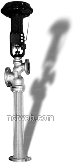
Type 426 Jet Compressors have automatically-controlled spindles. They are used when pressure, suction, or discharge conditions vary and it is necessary to control discharge pressure or flow. These units are made in 3 thru 24 inch sizes with flanged connections.

The spindle can be operated with a diaphragm, piston, or motor actuator using any standard instrument signal electric or pneumatic. The control can be activated by temperature, pressure, flow or suction to motive gas ratio.

Type 426 Compressor spindles are designed to act as temporary valves and provide right shut-off. For temperatures above 400F, spindle and seat should be hard-faced to resist wear.

These compressors are made in materials to fit operating conditions or as specified by customer. Standard materials are steel body and diffuser with stainless steel nozzle and spindle. Standard flange ratings are 300 lb. but other ratings can be furnished, as required.

Sizes and Dimensions - Type 426 Compressors
Size No. in Inches (Suction) Connections (Inches) Dimensions (Inches) Weight (Pounds)
Pressure Inlet Discharge Overall Lenght** Overall Width**
3 1-1/2 3 64-1/16 16 206
4 2 4 67-13/16 16 250
5 3 5 81-1/8 21-1/8 324
6 4 6 101 21-1/8 516
8 5 8 118-1/16 21-1/8 678
10 5 10 125-15/16 21-1/8 986
12 6 12 145-1/2 21-1/8 1176
14 8 14 166-5/16 21-1/8 1510
16 10 16 178-1/2 21-1/8 2350
** Includes diaphragm - type spindle controller.
Application Example:
Above is an example of the Type 426 Jet Compressors being used to boost the pressure of flash steam from a condensate receiver. Normally, this steam would be at atmospheric pressure. The two compressors use high pressure steam to entrain the flash steam and discharge at an intermediate pressure into a main which distributes the supply throughout a plant. An air operated pressure controller is affected by the pressure in the main and causes an increase or decrease in the pressure in the air line to the control mechanism on the compressor. A pressure relief valve acts as a guard against the building up of pressure in the receiver. The control system operates the two units in sequence and allows operation at a satisfactory entrainment ratio with varying capacities. The first one operates up to its full capacity before the second begins to operate. Upon load decrease, the second unit shuts down completely before the first unit begins to reduce.
Previous Page