Contact RCM Flow Meter Sales Department: 201-419-6111 Ext. 30 or sales@nciweb.com


FLO-GARD™ RCM INLINE FLOW SWITCHES

RCM Flow Switch
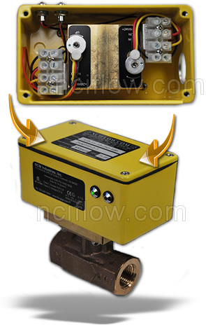
RCM's broad range of flow switches provide economical solutions for equipment protection and automation.

Our general purpose Flo-Gard II flow switches (liquid) reed switches make or break contacts by detecting the position of a magnet permanently attached to the bellow. Our reed switches can also be ordered for use in hazardous location (Option IS), when fitted with LED's (Option LED) it provides viewing at a glance when flow rate goes below or above the set point and makes field calibration easy.

Wide range of sizes and materials for optimal selection.
Choose one or two field adjustable switch set points from 0.5 gallons per hour (1/2") to 3000 GPM (8"). All switches are independently adjustable from 15% to 100% of range.

Maintenance-free Design
FLO-GARD™ flow switches operate on the differential pressure principle and have no bearing or sliding surfaces to corrode and stick. Normal maintenance is NOT required.

Low Installation Cost
FLO-GARD™ flow switches include a terminal strip and splash-proof junction box for making field connections, eliminating the cost of providing a field junction box.

RCM Flow Switch
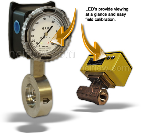
Standard Specifications: (General Purpose)
Accuracy: ± 3% F.S.
Repeatability: ± 1% F.S.
Pressure Max.: 400 psig (28.1 kg/cm2)
Pressure Min.: 10 psig (0.67 kg/cm2)
Temp. Max.: 212ºF (100ºC)
Temp. Min.: -30ºF (-34ºC)
Enclosure Rating: NEMA 4X / IP66

Electrical Rating:
Ambient Temp.: 120ºF (50ºC)
Setability: ± 5% F.S.
Hysteresis: ± 13% F.S.
Contact Rating:
10 Watts
175 Vdc max.
125 Vac max.
Current: 350 mA max. switching

Hazardous Location Specifications: (Option IS & LED)
  • Contact Rating: Vmax = 28V, Imax = 110mA, Pmax = 1.2W, Ci = 0uF, Li = 0uH
  • CSA / NRTLc: AEx ia IIC: Class I, Division I, Groups A, B, C & D
    Class II, Division I, Groups E, F & G
  • KEMA: Ex ia IIC: Zone 0, II 1G T4 0°C ≤ Ta ≤ 50°C ATEX EC Type Examination

Protect from freezing liquid

Open-CloseHow To Order

Select a) body size, b) end connections, c) material, d) maximum flow rate, e) options (if required) and f) number of switches.

  • (A) BODY SIZE: (pipe size at the meter inlet. Select from Standard Flow Ranges and Sizes)
  • (B) SERIES: (end connections) 1 - threaded units provided with FNPT connections standard. FBSP parallel threads available on request for bronze meters. 2 - wafer units mount between any standard 150 or 300 class flanges (or international equivalent).
  • (C) MATERIAL: 1 = Bronze 3 = Stainless steel (316)
  • D) FLOW RATE: (maximum) - Select from Standard Flow Ranges and Sizes, page 2. Prefix full scale with "M" for metric units.
  • E) OPTIONS: Select from table of Options. Note: For gas service, select option I and specify gas being-measured, inlet temperature and pressure
  • F) NUMBER OF SWITCHES: 1S2 - One single pole double throw switch 2S2 - Two single pole double throw switches

EXAMPLE: 3/4-1-20-A-1 S2

This is the catalog number for a 3/4" NPT Series 1000 Flo-Gage of bronze construction, flow range of 20 GPM maximum scale, equipped with optional seals of Viton, and one single-pole double throw reed switch.

 
Previous Page